info@gdaddtech.cn
+86-18566873215


Drilling clean holes in glass is less about force and more about controlling stress. Cracks usually start from micro chips at the entry edge, local overheating, or vibration that turns a small defect into a running fracture. A stable process combines correct glass selection, correct hole layout, diamond tooling, continuous cooling, and a finishing workflow that protects edges and hole rims through the full fabrication cycle.
For architectural and furniture fabrication, all cutting, hole drilling, notches, and edgework must be completed before heat treatment. Industry specifications for heat treated flat glass state that heat treated glass cannot be cut after tempering, but it can be furnished with holes and cutouts when those features are fabricated before heat treatment.
That single rule prevents a common failure: attempting to drill tempered glass after it has been fully tempered, which typically leads to immediate breakage.
Even a perfect drilling process can fail later if holes are placed too close to edges or corners. A widely used guideline aligned with ASTM C1048 requirements is:
Minimum distance from hole rim to nearest glass edge: 6 mm, also written as 1/4 inch, or 2 times the glass thickness, whichever is greater
Minimum distance between rims of adjacent holes: 3/8 inch or 2 times the glass thickness, whichever is greater
Holes near a corner require larger offsets to avoid stress concentration during heat treatment and installation
These rules reduce edge stress, limit breakout risk, and improve yield when parts move into tempering, laminating, or insulating unit assembly.
Glass drilling is typically done with diamond plated or diamond bonded core drills. The key is maintaining a water based coolant flow and preventing dry drilling. Practical shop guidance for diamond core drills emphasizes never running a diamond drill dry and using a coolant reservoir or ring to keep the drilling zone flooded.
Cooling does three jobs at once: it removes heat, flushes abrasive swarf, and reduces edge chipping by keeping the cut stable rather than grabbing.
There is no single universal rpm because it changes with core diameter, bond type, and machine stiffness. Many diamond tooling references recommend lower rpm ranges for glass core drilling and emphasize matching rpm to diameter to reduce chipping and overheating.
A practical way to standardize decisions is to lock the process around stable variables: coolant flow, minimal runout, and a feed that produces a steady slurry rather than powder. When a process produces powder, it is often running too dry, too fast, or with excessive pressure.
| Process checkpoint | Target control | What it prevents |
|---|---|---|
| Hole to edge distance | At least 6 mm or 2 times glass thickness | Edge cracks during drilling and tempering |
| Hole to hole spacing | At least 3/8 inch or 2 times glass thickness | Weak webs and breakout between holes |
| Coolant | Continuous wet drilling | Thermal shock and rim chipping |
| Tool type | Diamond core drill matched to diameter | Star cracks and uncontrolled breakout |
| Entry and exit control | Two sided drilling or reduced breakthrough force | Exit side blowout and large chips |
When you drill from one side only, the highest risk moment is breakthrough, when the remaining thin layer fractures and chips out. A two sided approach reduces exit defects by sharing the breakthrough event between two controlled cuts. Fabrication descriptions of professional two sided drilling systems highlight this as a standard method to reduce damage.
ADDTECH’s double head Glass Drilling Machine is designed around this logic: upper and lower drill bits work sequentially, with pneumatic clamping to stabilize the glass, and the worktable supports controlled movement. It can also accommodate two drill bit sizes to process different hole diameters on one glass piece, improving throughput without frequent changeover.
Many chips that appear as drilling defects actually occur later during handling, washing, tempering, or installation, especially when edges are unfinished. A controlled edging step removes micro cracks and stabilizes the perimeter, including the area around holes and cutouts.
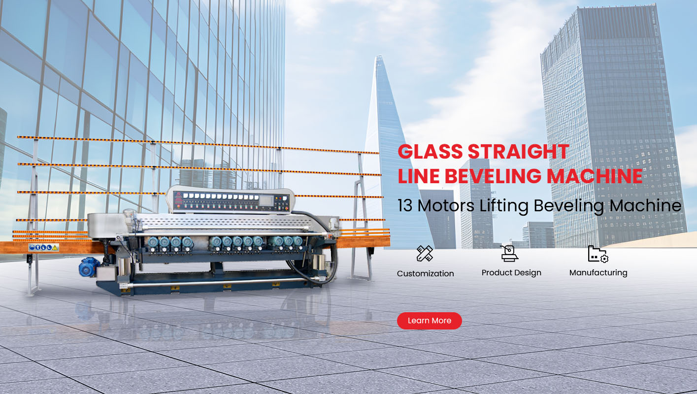
This is where Glass Edging Machine long tail selection matters. For consistent finishing, many workshops specify an 11 Motors Glass Straight Line Edging Machine with PLC control and digital display so operators can keep polishing and edge removal stable across batches. ADDTECH lists straight line edging equipment with CE configuration options, PLC control availability, and heavy duty structural design features intended to support repeatable grinding quality.
For operations that run mixed orders, it also helps to standardize tooling and wheel speed logic. Diamond wheel peripheral speed recommendations for glass grinding are often stated in the 40 to 60 meters per second range as a process target, supporting stable material removal without excessive heat.
From a production perspective, hole drilling quality is not a single machine issue. It is a line issue. ADDTECH positions its portfolio around core fabrication steps including drilling and edging, so the process can be built as a repeatable workflow rather than isolated stations. The company profile describes specialization across straight edge, bevel, round edge, special shape, and drilling machines, supporting a consistent equipment ecosystem for glass fabrication lines.
Clean glass holes come from stress control: correct hole placement, wet diamond drilling, stable two sided breakthrough, and edging that removes micro defects before the panel sees handling and heat treatment. When your line combines a controlled drilling station with a consistent glass edging Machine finishing step, you protect both yield and appearance across bulk production. ADDTECH can support this workflow with drilling machines built for stable clamping and sequential drilling, plus edging solutions designed for repeatable finishing and production consistency.